Translate

Wednesday, February 24, 2016

APA Micro Layout (Part 11) Operation

After three months of building, my Micro Layout for the contest of the german modelrailroad magazine MIBA is finally finished.


The track arrangement is a so-called Inglenook switching puzzle. More details about building and operating this kind of layout may be found on Adian Wymann's The Model Railways Shunting Puzzles Website.


The photo above shows the entire layout in a space of 70 x 30 cm (2'4" x 1')


The fiddle yard has the same dimensions but is not scenicked .... yet. The rules for the contest only mentioned a fiddle yard, the same size as the layout, attached to one side or half the size on each side. The two tracks through the crossing are the drill tracks.


The advantage of the APA boxes is that they are real boxes with a lid. I used the boxes sideways so there is more height for the layout. The box lids serve a double purpose, dust and damage protection.


 The interior of the boxes are lighted with one fluorescent tube each, attached to the valance.


As for operation, I kept it simple. The minimal Inglenook that I have calls for five cars, placed on random spots on the layout. Three cars are to be switched into a departing train. There are random car generators on the internet to select the cars, but this involves a computer next to the layout. I simply added one car for total of six. I also choose cars in different colors. I painted a wooden dice with the same colors than the cars. This is my random selector. On a sheet of paper I only note the order in which the cars are to be placed behind the locomotive.


At the beginning of an operating session, the six cars are placed randomly on the layout. Now I throw the dice. Then I note the color of the first car. Then the second and the third. Now I switch the cars in the order I have thrown the dice. This implies some challenging switching moves, as the remaining cars must be replaced where they stood initially.

The original Inglenook with a 5-3-3 arrangement generates some 40,000+ configurations. My version still 120. That's enough for some relaxing killing time.


APA Micro Layout (Part 10) Weathering and Details

A busy scene like a car repair shop needs lots of details to be convincing.


This is a good way to use some of your surplus bits and pieces from previous projects. In some kits there are always alternative or spare parts. I never throw these away, but keep them in compartment boxes for "later" use. Some will never find their way out of the box. These are normally hatches, doors, plastic wheelsets that have been replaced with metal ones, brake cylinders and wheels, plastic couplers etc. Some decent weathering with rust and grime powders or washes make them suitable to represent the junk and litter sometimes needed alongside the tracks. Here for my repair shop I mainly needed parts that are needed in such a shop. i.e. all kinds of car parts like shown in the picutre above.

Placed on pallets or racks they give a feel of what's happening there.


The paved area outside the car shop was modeled using wall repair compound. After it had dried thoroughly, I painted it with grey asphalt color. Because the plain grey paint is too uniform, I usually use "Dirt" and "Soot" powders, which I apply by dipping a wide brush into the powder and dabbing it on the surface of the road or area to be weathered.


Applying dust and dirt dulls the color down quite a bit. Then I added some black soot powder to simulate grime and oil.


I also installed a small section of track with two additional rails installed to stagger the wheelsets. These are Athearn plastic wheels with metal axles. I always replace these because they get attracted by the uncoupling magnets. Painted a rust color, they get a new life as spare wheels on my workshop scenes. I glued the brake wheels and cylinders to pallets. These are spare parts and should not lie on the bare ground.


Some other details are stacks of lumber for replacing damaged car floors or sidings. Spare trucks and boxes with spare parts complete the scene.


Different figures from Preiser give life to the scene. The trick is to make them do or contemplate about something.


A Hobo is filing through a trash bin for something to eat.


The first cars have arrived on the repair tracks......


...with some more to arrive. This will be a busy day!


APA Micro Layout (Part 9) Uncoupling magnets

Another small evening project was installing magnetic uncouplers in the fiddle yard box of my contest micro layout. I have a doule slip crossing to save on space that two ordinary turnouts otherwise would use.

A pair of Kadee Magne Matic uncouplers (#322) would do the trick. 


Unfortunately I only had code 83 uncouplers and my track is code 100. So I had to shim the magnets to rise their height to were it needed to be.


Positioning the magnets is critical, because they need to be centered between the rails, for the uncoupling levers to work properly.


I used a contact cement to glue both the shims and the magnets to the ties.


With the uncouplers in place, I don't have to reach inside the layout box to uncouple cars with a scewer. The tight arrangement of the details makes it easier to uncouple hands-free.


Friday, February 12, 2016

APA Micro Layout (Part 8 Weathering the Highway overpass)

To hide the entry/exit of the layout I will install a highway overpass with concrete footings. These conceal the hole from the viewers side.


The roadway will also cast a shadow over the entrance so it will not be so obvious.


After assembly, I first brush-painted the bridge with a concrete color.


Then I applied some decals with signs and slogans that are usually found in such places. After the decals had dried I oversprayed it with Testors Dullcote. The matte finish of the Dullcote gives the surface some tooth for the weathering powders and pigments to stick to. With a bristled brush I dusted the parts with burnt umber and sienna pigments. If you inspect a concrete bridge or abutments closely, you find that all the dust and grime gets washed down with every rainfall. These different colored streaks were the effect I tried to recreate.


I sat the bridge upright and loaded a wide brush with Isopropanol Alcohol and squeezed it to the top of the pilasters and the lower concrete wall. The liquid ran down the side, washing some of the pigments down. The alcohol also dissolved some of the concrete color and bleached it out. I repeated the process until the desired effect was achieved. I also alternated between a black wash and the liquid from cleaning my brushes. You cannot overdo it if you use the blacks sparingly.


Then I turned my attention to the roadbed. I first pencilled the white separation lines with a white pencil using a straight edge. I prefer this technique over spraying them with white color. The pencil leaves a more faded appearance. Then I gave the road a black wash to highlight the expansion cuts and to tone the concrete color down. One important other feature are the rubber marks. To recreate these I used a fine brush to apply black powdered chalks to the running lines of the car tires. I used my finger tip to rub the powder all along the direction of traffic. With a brush loaded with Alcohol I dabbed the liquid randomly onto the roadbed. This created some irregular dried puddles.


The overpass will be a double lane into one direction and the opposite direction will be in the fiddle yard box. I think this is more convincing than just one lane in each direction. The cars are not correct for the era I will model.

Please drop by regularly for updates. Thank You!


Thursday, February 11, 2016

APA Micro Layout (Part 7) Ballast and Asphalt work area

To create the open air work area I applied a layer of repair putti or spackle to the height of the rails with a spatula, taking care to spread it out evenly. Before the putti cured I pushed an old truck over the track to free the flangeways.


The photo below shows the overall size of the layout with the work area.


I painted the ties with Floquil Tie brown markers and the rails got a coat of rail brown and rust.


With a plastic spoon I applied the ballast between the ties.  Then I misted the whole area with wet water (a few drops of Isopropyl Alcohol added to distilled water). I also add Isopropyl Alcohol to my scenic cement mix with consists of 1 part Matte Medium and 7 parts distilled water. I apply the mix with a plastic pipette. The wet water lets the matte medium seep into the ballast and bonds it securely.


After the ballast was dry I continued with the surrounding scenery. My preferred material for this is earth/sand colored grout sifted over a coat of white glue and then misted with wet water. Before the grout dries I sprinkle ground foam, sand and other scenery materials over it.


After drying the scene looks like in the picture above.


Then I painted the work area with asphalt grey color from HEKI.


Almost done. Watch for the update.


APA Micro Layout (Part 6) Trackwork and Turnout controls

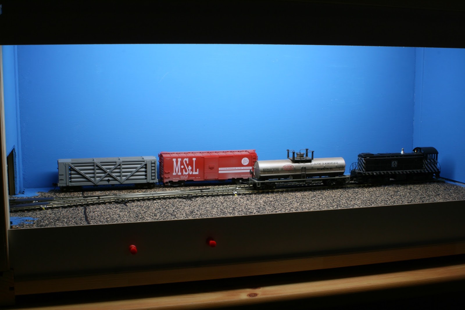
OK, well here is some progress on my micro layout. After fiddling around with different turnouts and track pieces I still had in my surplus, I finally ended up with two PECO Setrack turnouts and some curves and straight pieces. The restricted space on the micro layout called for sharp radius turnouts and curves to fit properly.


To ease some curves I also used bits of flex track.
On the fiddle yard box I used a standard double slip crossing and pieces of flex track. For the contest, the fiddle box will not be scenicked. But instead of two straight tracks where I could swap cars and engines using a cassette or in my case a PECO Loco Lift, I installed the crossing. I'm not quite set on the scenery for now. This prbably distills out during construction.


My preferred method of fixing the track to the cork roadbed is white carpenters glue. I usually use the strong, waterproof-when-dry, type. All containers heavy enough to hold the track down into the glue are appropriate. Also visible in the picture below are my basic tools and liquids for track work. Xuron rail cutter, Xacto knife with #11 blade for cutting and removing the plastic ties, a jewelers file for smoothing the cut edges of the rails and finally Matte Medium to bond the ballast in place.


After the glue has dried completely I drilled small holes to either sides of the tracks to accept the feeder wires. I don't rely on the conductivity of railjoiners, so I feed every piece of rail that's connected with a rail joiner. This insures that I have current on every bit of track. This is especially important when using short locomotives or where slow moves are required like on a switching layout like this one.


Then I solder the feeder wires to the outside of the rails and pull the wires tight from the underside of the baseboard.
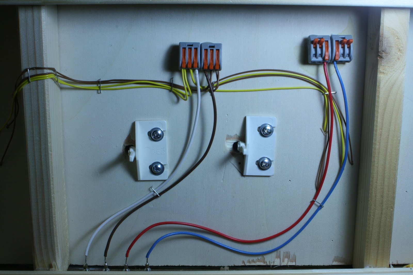
On the underside I shorten the feeder wires and staple them to the board so they don't dangle down. To connect the feeders to the bus wire I use terminal blocks by WAGO. They are standard lighting connector for 2, 3 and 5 conducts. (WAGO SOSElectronic. This link is only for reference. I'm in no way connected to this company) A similar product should be available in your country also. I attach the terminal blocks to the wood surface of the baseboard with hot glue. The advantage here is that I may add wires or rearrange very easily by opening the clip of the respective conduct.


The power supply is fed in from the rear of the box. For reference, the brown and yellow feeders are the trackpower and the red and blue wires are 12-14 VAC current for the lights.

Turnout Control

In an attempt to keep everthing simple, I installed Rix Products PTL (Pivoting Turnout Linkage). They are actuated by choke rods.


Before glueing the turnouts in place I drilled a 10 mm hole into the baseboard for the pivot of the linkage. Positioning of the PTL was made easy by using double sided tape to hold to the underside of the mounting pad.


These turnout controls consist of only four pieces, the mounting pad, the pivot which is clipped to the pad, a piece of piano wire and a small screw to hold the wire to the pivot. Two mounting screws for the pad are also included.


The only thing to take care of is to stick the pivot with the piano wire through the hole in the switch tie correctly from underneath. The PECO turnouts have a spring installed so that the closure rails always close firmly to the stock rails. The double sided tape holds the linkage in place and may be adjusted before drilling the holes for the mounting screws.


I fabricated the choke rods from 2 mm brass tube, 1 mm brass rod and push pins. A piece of brass rod is soldered to one end of the tube, bent 45° and inserted in one of the three holes of the pivot. The tube is then pushed through the fascia and cut to size. The push pin is inserted into the tube and soldered. This is the handle for actuating the pivot and throwing the turnout.


The photo above shows the finished wiring and the turnout controls.

Stay tuned for more progress on the layout.